BluetoothTM is a complex communication protocol to implement. Luckily, all I needed to know was the interface between L2CAP and LFCOMM. In order to use L2CAP efficiently, one must have some understanding of how it interacts with its upper and lower layers. Here, I would like to describe briefly only the different interfaces that have been reused and modified in GBI. They are also the most basic and essential operations in BluetoothTM.
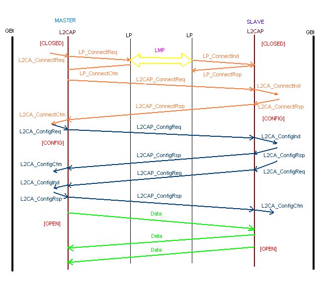
The colourful diagram above mainly shows the connection and configuration interfaces and the four phases of service primitive events that occur in each of them.
In the beginning no connection is formed, therefore it is a [CLOSED] state. When the Master GBI first execute its poin_entry_Run(), a Connect Request (ConnectReq) tagged packet is sent to L2CAP. This packet would pass through all the lower layers of Bluetooth such as LMP and the Baseband to the Slave (another Bluetooth enabled device). A request service in Bluetooth would be the first phase of an event, such as a connection request here. When this request has been received by the lower layer of another Bluetooth it would send an indication event to the protocol layer directly above it instead of the original request. An example of an indication would be the Connect Indication (ConnectInd) packet send from the L2CAP layer up to the Slave GBI. If an indication has been received then a response would be sent back else it is not Bluetooth. Therefore the Slave GBI would send back a Connection Response (ConnectRsp) packet to L2CAP. Eventually this response packet would be received by the Master Bluetooth which is the sender of the connection request event. What is more, when the lower layer of Bluetooth has received a response it would send a confirmation to the protocol layer directly above it in order to confirm that a request has been received by the other Bluetooth. The last part of the connection stage would be the arrival of the Connection Confirm (ConnectCfm) packet to the Master GBI from L2CAP.
The connection is not established yet, a Bluetooth device still has to configure with the other. When the Master GBI has received a confirm for its connection request, it would move on to the configuration stage of the interface. The [CONFIG] state. The Master GBI would now send the second request known as the Configuration Request (ConfigReq) packet to the Slave GBI. The event phases are the same as the connection request apart from one difference. A Configuration Indication (ConfigInd) packet would be received by the Slave GBI from the L2CAP. Immediately a Configuration Response (ConfigRsp) would be returned. The difference is that sometimes not only a configuration request is returned, the receiver, Slave GBI in this case, would also send another configuration request to the Master. This mechanism is depicted in the above diagram. However, the actual implementation of GBI only has one configuration request. This is because one configuration request is enough in GBI. However, another difference is that GBI would send a read request packet to the L2CAP instead of a configuration request packet. More about read requests later. By now Master GBI would have received the Configuration Confirm (ConfigCfm) packet. Now, Master and Slave are said to be connected, the state of the interface would be [OPEN] and the connection_established variable/flag in GBI should be set to true (1). The disconnect event is not implemented since it would never be needed.
It is no use to has an opened communicaton channel but no data could be transferred across. Therefore we would require both read and write capabilities implemented in GBI.
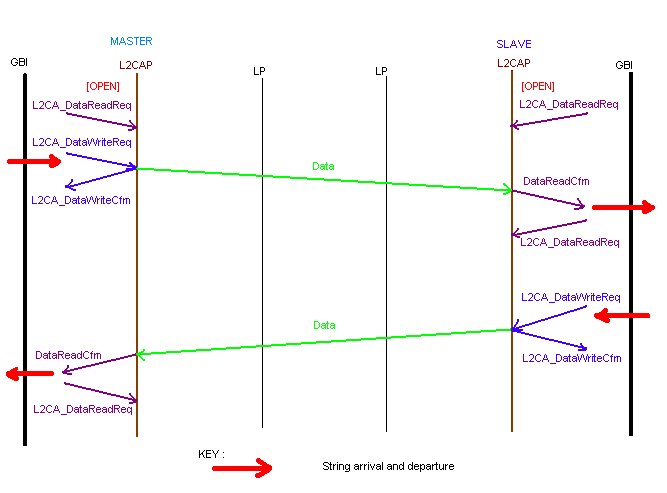
After the configuration stage, both bluetooth enabled devices would now have a Read Request (DataReadReq) packet waiting at the L2CAP layers. This means that both devices are ready to receive data (a string) from the upper layer directly above it such as the GBI-Test module or simply the game devices. When a string has finally arrived and entered GBI via its Input port (top left big red arrow), the string would be copied into the in_String buffer which is a 20 bytes array. Then a Write Request (DataWriteReq) packet would be prepared. But before this packet is sent the string in the in_String buffer would need to be copied into the OutBuffer of the write request packet byte by byte. Now the write request packet contains the string from a game device and so this string would be sent to the lower layers, through the atmosphere, and received by those devices that have a Data Read Request waiting at their L2CAP layers. L2CAP would immediately send a Write Confirm (DataWriteCfm) packet to GBI to confirm that the string has been sent. Nothing needs to be done for the Write Confirm packet by GBI.
On the other hand, when data (a string) has arrived at the L2CAP layer that has a read request awaiting, GBI would recieve a Read Confirm (DataReadCfm) packet from L2CAP. The string would also be copied byte by byte from the InBuffer of the Read Request packet into the out_String buffer in GBI. The number of bytes transferred to InBuffer is saved in the N parameter. GBI can now send this string via its Output port to the other game device (top right big red arrow).
By now a string has been sent succesfully from one device to another. This is not good enough. The rule is that whenever GBI has received a string, it must immediately send another Read Request to its L2CAP again so that it could receive another string in the future. This is called the Read Request (DataReadReq) packet.
The lower half of this diagram is a reversal of the upper half. A string has entered Slave GBI (lower right big red arrow) and it is received by Master. You may already be asking "Where is the Read Request at the Master L2CAP ?!", the first Read Request sent after the configuration still has not been used, it is still waiting at the Master L2CAP! Now the string would be read by GBI and sent to the game device (lower left big red arrow). Another Read Request is sent to the L2CAP.