Application - Implementation
This page documents the implementation work that was carried in VCC. Click here to return to the Main Application Page.
Use these links to skip to specific sections of this page.
Overall Analysis/Review
Implementation of the entire functionality proposed in the original design proved to be over-ambitious, and was not achieved. This was partly due to the distribution of the members of the group between tasks - we only had one person working on the application where other groups had two, and partly to do with problems experienced during implementation, which increased the times taken to implement various blocks.
There were several major things that I didn't get around to, but would have liked to. Firstly, I didn't get close to thinking about integrating what I did with the robot. I didn't manage to implement the communicationally intensive version of the system either; at one point this looked possible, but in the end it was a choice between integration with Bluetooth and this, and I considered Bluetooth more pivotal.
However, I did manage to successfully implement what I consider to be the core functionality of the system - the most important and/or challenging aspects of it. This includes a complete edge-detection system, and a scheme for locating a numberplate and recognising characters within it. These blocks were successfully integrated with the Bluetooth stack implemented elsewhere in the project.
All the VCC blocks which I implemented can be found in the library: "/home/slipc/alpsSLIP/CARMA" , along with high level behaviours and simulations.
Computationally Intensive System
Communicationally Intensive System
Due to the time constraints on the project and the problems experienced in implementing the computational system, it proved impossible to complete the communicationally intensive version of the system. In essence this only required the integration of a JPEG encoder with the robot blocks. However, here was insufficient time available to investigate this in any detail.
Implementation of the Computational System - Overview
Return to Top of Page
The main high-level blocks that have been implemented are the Bitmap Loader, the Edge Detection block, and the Registration Number Recognition block. Each of these blocks will be explained in greater detail, but first there are some general points I should make about implementing the system.
- Image Passing. The largest problem I encountered within VCC was passing images between blocks. The images are 2-dimensional arrays of 8-bit unsigned characters, and the main difficulty occurs when passing them from a whitebox C block to a blackbox C++ one, or vice versa - passing them between 2 whitebox C blocks is straight-forward.
The method I utilise is simple enough, but I had to try numerous alternatives which didn't work until I found it - the VCC manuals weren't really much help. I use a declared a type which is an alias for an array of 32-bit integers, and convert the 2-dimensional unsigned character arrays to and from this type each time I pass them between blocks. This means building groups of four unsigned characters into one integer; it is possible to pass arrays of 8-bit values, but I discovered that VCC actually converts the 8-bit values into 32-bit ones when it passes them. This would have had an impact on the mapping process, as all communications of images would have required four times as much bandwidth as they should do.
Getting an Image
Return to Top of Page
My original intention was to grab images "real time" using a distinct block in the VCC system. I didn't achieve this goal, for two main reasons:
- VCC is not intended to be interfaced with hardware. It operates under its own notion of time which is tailored to the simulation it is running, whilst hardware events are strictly real time. This results in very unpredictable behaviour when trying to interface the two. I think this problem has been solved to some degree elsewhere by implementing a block which forces VCC into acting something like real-time.
Even if this problem had been solved, little would have been gained by implementing the block. Images would have been captured using functions from the Video for Windows header files. For mapping purposes VCC would not have been able to calculate delays for these functions; instead we would have had to use an inaccurate estimate for their delay.
- Libraries written for image capture in Windows do not allow easy access to individual pixels of images. Accessing and manipulating individual pixel values is essential for any edge detection and character recognition functions. However, all the library functions bundle the images up into seemingly endless layers of structures which prevent easy access to individual pixel values. I think this is an intentional measure to protect te functionality of the functions.
I think Group A have written some code which solves this issue; you should be able to check if and how on their web-site
I spent a reasonable amount of time at the beginning of the implementation work looking at ways of being able to grab images from within the simulation, and these were the main problems I discovered. I felt that they may have been solvable, but to do so would have taken up a large amount of the implementation effort, and this was not really justifiable. The main point of the implementation was the character recognition stuff, not grabbing images!
Having discovered all this I settled on grabbing images into bitmap files from outside VCC. I then implemented a block to read the images into VCC from those bitmap files - the Bitmap Loader block:
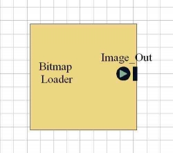 Bitmap is a nice format to use because it has a simple format, and is therefore easy to get at and use. The basic format of a bitmap file is a preamble of header information (including palette information) followed by the bytes corresponding to the pixels of the image.
The block just opens the input bitmap file, reads the palette information from the header, then skips past the headers and reads the image into a two dimensional array of 8-bit unsigned characters (pixel values can range from 0-255, so 8-bits is the smallest data-type that can store them). This array (the image) is then posted on to the next block in the system.
Edge Detection
Return to Top of Page
The Underlying Behaviour
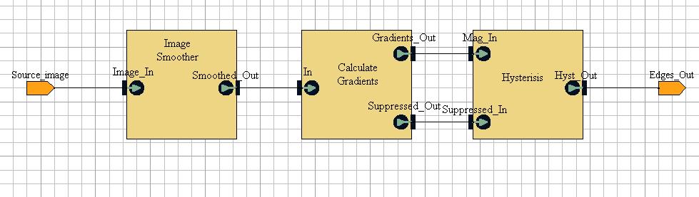
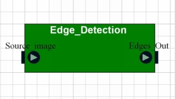
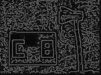
The Edge Detection block takes the input image from the Bitmap Loader block and produces an image containing the major edges within it. The scheme is based on the Canny method, and much of the basic code was actually written by Morten; I then migrated it into VCC and tailored it to the problem, and to interface with other code. The Canny method claims to be an optimal edge detector. Each step in the scheme is contained in a separate block, each of which will be considered individually. I'll try not to go into too much technical detail about the individual steps of the Canny scheme - if you are really interested there's a lot of coverage of it on the web.
Try this page for an alphabetical list of links to explanations of various edge detection terms and methods.
Analysis :
The overall algorithm doesn't follow the Canny scheme that closely in parts - different steps adhered to the original scheme more or less strictly than others.
The following factors can affect edge-detection schemes such as this:
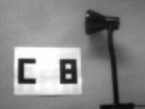
- Contrast - If the colour of an object is similar to the colour of its background it may be more difficult to distinguish its edges. Use of the scheme has been to locate white "numberplates" against light grey backgrounds.
- Ambient Lighting - Low ambient light levels may lead to a deterioration in perfromance. Light levels have usually been quite bright when the scheme has been run, but it has worked under some intentionally induced dimmer conditions as well.
During my usage of it, the block has always managed to identify numberplate and character edges. Under some conditions it produces gaps in the edges, but these are rare and generally small (1 or 2 pixels).
Gaussian Smoothing
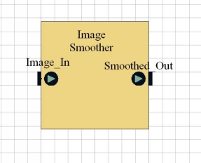
The Gaussian Smoothing block is a whitebox C block which blurs the original image to remove detail and noise (pixels which are very different to those surrounding them are eliminated). The algorithm replaces the value of each pixel with an average value of the pixels surrounding it. Initially, it produces a kernel which is a discrete approximation of the continuous Gaussian function for a particular standard deviation (I normally use 0.8 which seems fine, but the value can be changed if necessary.) This kernel is then applied to every pixel and its neighbours in the image, producing a new "smoothed" value for each pixel.
The code for this block originally used the ceil function from the "maths.h" library (the function just calculates the ceiling value of a value). However, when mapping to a platform architecture VCC cannot calculate delays for library functions, so I implemented my own version of the function, which was simple enough to do (4 lines of code!).
Analysis :
This is a very well established technique in the context of image manipulation, and is relatively simple to code, so as you would expect there are no problems with the block's performance and efficiency.
It is worth noting, however, that the bitmap images that are captured generally have very low levels of noise and distortion. In view of this, if the scheme proves to be too computationally intensive it may be worth investigating the performance of the edge-detection method without this block.
Computation of Gradients
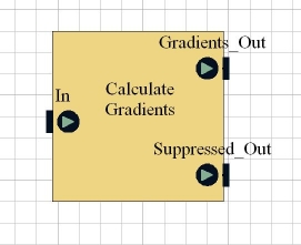
The Compute Gradients block takes the Gaussian smoothed image and computes gradient values for every pixel. The gradient value for a pixel is a measure of the amount of change in the pixel values surrounding that pixel (where edges are present there should be a sharp change in pixel values). For each pixel, the block calculates a gradient for the x-direction and one for the y-direction, then combines the two. Gradient values are then thresholded, i.e. values above a threshold value are interpreted as potential edges, whilst edges below the value are not. These gradient values also give an indication of the direction of the edge.
Once the edges have been identified, non-maximal suppression is applied to them. This is a process which follows a line, and eliminates pixels which are not on the "ridge" of that line in order to thin it. The process just gives each line a more specific representation.
The block has two outputs. Suppressed_Out is the final image as shown above. Gradients_Out is an intermediate image which is created and used in the calculation of the final image; it is required by the Hysteresis block for its calculations.
This block was implemented in blackbox C++. This was necessary as it utilised functions from the "maths.h" library which were too complex to re-implement, and the version of VCC that we were using would not allow standard libraries to be used with whitebox C code. These functions were exp and atan2. For mapping purposes this means that a delay cannot be calculated for the code; instead an estimated delay value will have to be associated with the block.
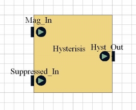
Hysteresis
Dictionary definition: hys�ter�e�sis : The lagging of an effect behind its cause, as when the change in magnetism of a body lags behind changes in the magnetic field.
The Hysteresis block takes all the edges identified by the Compute Gradients block as input. Its purpose is to combine edges that have been split into fragments during the detection process back into a single edge again. During this process the block also discards a lot of the edges that have been identified in the process to leave only the major lines.
Analysis :
This block has the greatest impact on the lines which are finally identified by the scheme. The first two blocks will always identify the major edges in an image, plus a great many more possible ones. It is this block's responsibility to discard edges and leave only the "real" edges in the image, by way of a thresholding process. Initially it took a fair amount of trial and error to find a threshold level which would result in the elimination of the vast majority of meaningless edges whilst not eradicating any of the real ones. Since a suitable threshold value has been identified, though, it has not proved necessary to alter it for different images - its results appear consistent.
Registration Number Extraction
Return to Top of Page
| Input |
|
The Block |
|
Output |
 |
|
 |
|
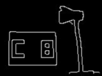
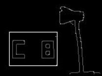
"CB" |
The Underlying Behaviour
Finding the Numberplate
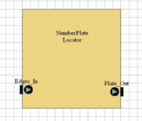
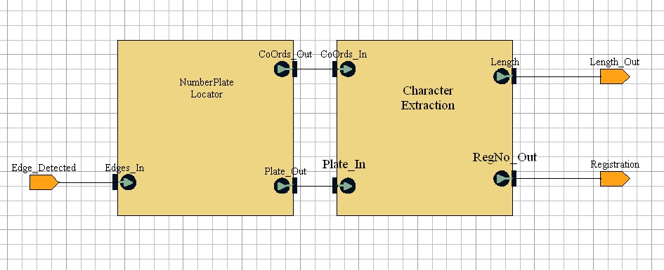
The Numberplate Locator block attempts to use the edges identified by the Edge_Detection block to identify the position of the numberplate in the image.
Essentially, this is done by:
- identifying all the polygons made by the edges, then
- finding the polygon which approximates best to the known dimensions of a numberplate.
To identify polygons we search through the input image (containing just the edges identified by the edge-detection scheme) until we find a pixel with an edge value. We then follow the path of adjacent edge valued pixels until:
- We arrive back at the pixel we started from. This means that we have found a polygon.
- We reach a pixel that has no adjacent edge pixels. This means that this set of edge pixels traversed was probably not a polygon.
This process is repeated until no more edge-valued pixels can be found in the image. As each edge is followed the edge-valued pixels are replaced with an intermediate, "possible-edge" value. This prevents an edge being considered more than once..
Once a polygon is found, its width/height ratio is calculated. This ratio is compared to the known width/height ratio for a numberplate - the polygon with the closest ratio is identified as the numberplate, and replaced with the smallest rectangle which will bound it.
Analysis :
This block was my first attempt at solving the problem, and I expected it to be too simplistic and require considerable enhancement. However, once it was integrated with the edge-detection block I found it to work well unless some of the numberplate edge was obscured in the original image. Nevertheless, I think this block is the most naive of any in the system, and it would be the first one that I would try and re-implement to improve the numberplate recognition process.
Weaknesses I have identified are:
- If other rectangles with similar dimensions to a numberplate are present in the image, they are just as likely to be identified as the numberplate as the actual numberplate is.
- The algorithm lacks a sophisticated strategy to deal with breaks in the line. This makes it reliant on successful edge-detection - if the edge-detection fails to highlight the numberplate edge with a continuous line it is quite likely that the algorithm will fail to identify it.
- The algorithm relies on the numberplate being straight. If the numberplate is at an angle in the image, it will not have a good width/height ratio and is unlikely to emerge as the best candidate.
- The numberplate will consider any irregular polygon as a candidate for the numberplate. Ideally it would consider only those polygons which approximate to a rectangular shape.
I think that a really good solution to this problem would probably have quite a lot of Artificial Intelligence behind it, for example fuzzy logic. It should probably try and identify straight lines by way of their gradients and determine which lines could be interpreted as making up rectangles. Given accurate information about gradients, it would be simple enough to calculate the lengths of slanted lines, so the height/ratio method might be appropriate still. Dealing with other rectangles in the image would require some analysis of what lies inside the rectangle.
Character Recognition
| Input |
|
The Block |
|
Output |
 |
|
 |
|
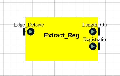
The length of the registration number, i.e. the number of charcters it contains ( in this example 2 ).....
.... and the registration number itself ( in this example "CB" ). |
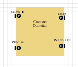
The Character Extraction block tries to identify characters within the region identified as the numberplate by the Numberplate Locator block.
There is an integer defined for the block to indicate the number of characters present on a plate. The block divides the plate into this number of equal horizontal sections, and tries to identify a charcter in each section. It does this by:
- Bounding the character. The algortihm searches for the highest, lowest, leftmost and rightmost edge pixels within the current section. It uses the positions of these pixels to bound the character in a rectangle.
- This rectangle is then considered as a number of component rectangles, arranged in a 3*5 grid as shown below.
-
In each section of the grid, the number of pixels with a value darker than a threshold value is counted. This value is then calculated as a percentage of the total number of pixels in a section. If this value is higher than a threshold percentage the block is taken to be part of the character, otherwise it is not.
-
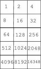 |
Each position within the grid has a value as shown. The values of the sections which are seen to be part of the block are summed, to give a total value for the character. This value is compared against a list of reference values to (hopefully) identify the character. The values for the sections of the grid have been chosen so that every different combination of them has a unique value.
|
This link leads to a reference page of the character set used and its numeric values.
Analysis :
As with numberplate location, this performance of this block is
greatly reduced if the numberplate is not well-aligned with the
horizontal and vertical axes of the camera. If this condition is not
met, the sectors identified by the algorithm will not correspond well
with the actual sectors of the character, and the percentage of dark
pixels calculated will be inaccurate.
Performance of this block is also limited by the resolution of
the camera used. If the resolution is low, then the number of pixels
contained within each identified sector of the character will be
low. As each pixel is only identified as light or dark, individual
pixels have a much greater effect on the overall percentage calculated
for a sector when that sector contains only a low number of pixels.
An alternative strategy for this block would be to try and deduce
characters directly from their outlines. This would require a much
more sophisticated algorithm, and would again probably require the use
of some Artificial Intelligence techniques, such as "fuzzy logic". An
implementation of such a strategy was too complex for the scope of
this project.
Interfacing with Bluetooth
Return to Top of Page
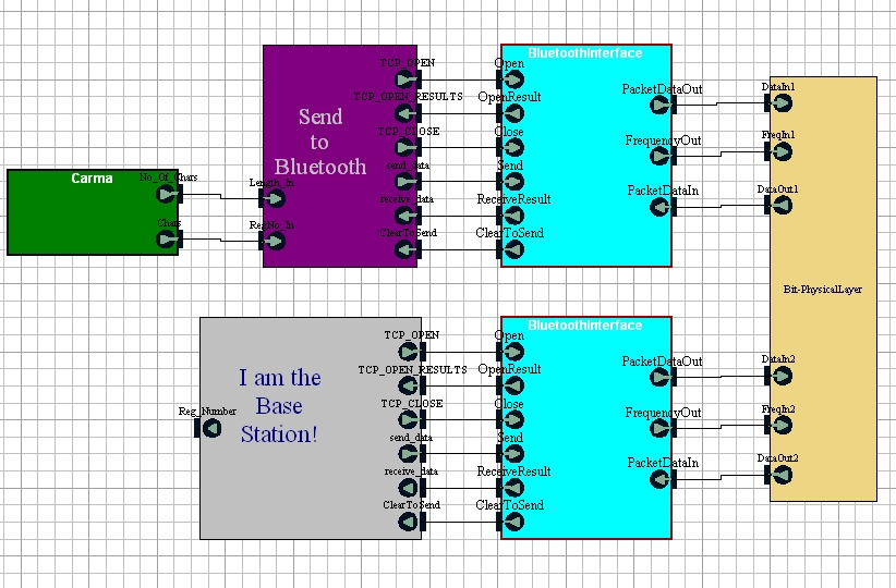
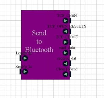 The Bluetooth Send block interfaces the main CARMA block to the Bluetooth stack. It waits until it is passed a registration number and the length of that number of that number from the CARMA block. It then creates a new packet containing the registration number and waits for a Clear_To_Send signal from the base-station. Once it receives this signal, it transmits the packet over Bluetooth.
The Base Station
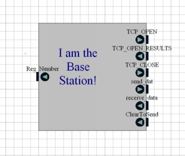 (Sorry about the random block name...). The Base Station block doesn't do much more than receive transmitted registration numbers from the Bluetooth stack. It acts as the master device in the Bluetooth communications, and as such is responsible for maintaining and controlling the connection with the robot. When a packet is received from Bluetooth, the block extracts the registration number from it, and posts it on its output port to allow verification of its transmission.