Mapping the CARMA Application
Overview
The Car-park Attendant Robot (Model A) (CARMA) application is Group C's chosen task for the project. The application is described in detail on the Application page. Its most important behaviour set, and the one which our group has spent most time developing is that of the numberplate recognition. In essence, the recognition behaviour takes an image, searches for a number plate using edge-detection algorithms and then extracts letters and/or numbers from the numberplate. The behaviour developed by Alan to acheive this is shown below:
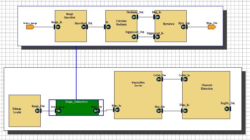
Fig. 6 - Application Behaviour
There are a number of blocks to take note of for mapping. A short description of each follows, although a more detailed description can be found on the Application Page.
- The Bitmap Loader block does not require to be mapped. In fact, this block cannot be mapped, as VCC does not map blocks with no input ports. This does not matter, since the block would be relaced with the image-capturing software from a camera if a full-scale prototype was developed.
- The Edge-Detection block decomposes to the following three blocks:
- The Image Smoother block takes a bitmap image and smooths the output
- The Calculate Gradients block takes the smoothed image and calculates the colour gradients within the image
- The Hysteresis block then finds the edges within the image.
- The Numberplate Locater block takes the edges produced by the Edge-Detection block and locates the numberplate from within the image
- The Character Extraction block then finds the characters displayed on the numberplate.
The blocks can be mapped to different architectural resources in the SH2 platform depending on the type of calculations done in the block, and the time required to run these calculations.
- The SH2 processor itself will take the bulk of the processing. It is a multi-purpose processor capable of running non-complex instructions at a reasonable speed.
- The DSP processor is designed to run more complex calculations at a higher speed, however, you must trade-off against the time taken for the extra bus transfers that this requires between the SH2 and the DSP.
- Specialised ASICs (Application Specific Integrated Circuits) can be set up to do the processing of specific blocks in a constant time, therefore reducing the load on the processors.
Mapping to the SH2 Platform
Mapping of the Application behaviour to the SH2 platform was fairly straightforward once Alan had the Application behaviour set up to reliably pass functional simulations. There were a number of different simulations set up, using different mapping configurations. The 'Calculate Gradients' block is always mapped to the DSP processor, since it uses a delay script, and this has only been calculated for the DSP processor setup.
A further point to note is that the initial 'Image Smoothing' block in the application was always taking a significant time to run. For example, the image in Fig. 7 shows a possible mapping with the image smoothing block mapped to the faster DSP processor.
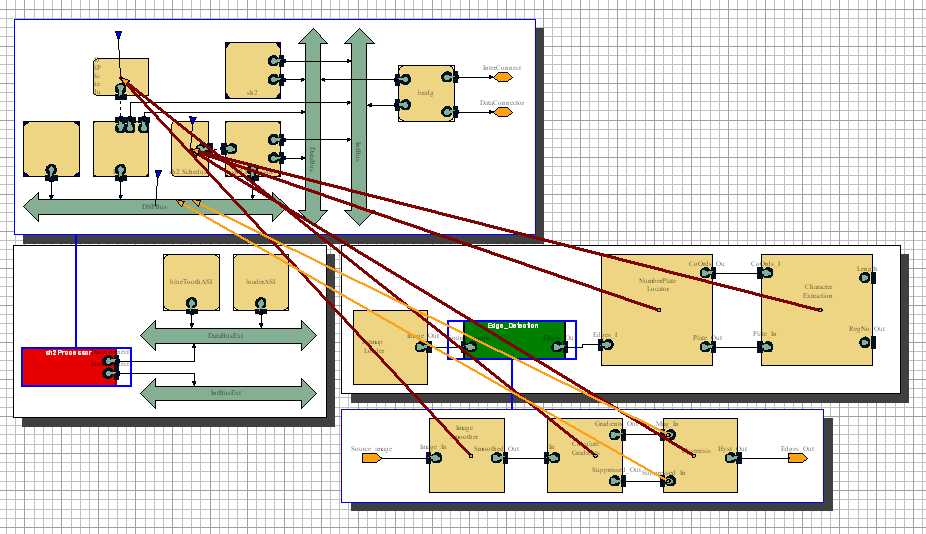
Fig. 7 - Image smoothing mapped to DSP
Even here the results, shown in Fig. 8 below show that the image smoothing block (the timing of which is reprented by the long first line) is a significant bottleneck in the system. Consequently, the decision was made to map this behaviour to an ASIC outside the processor block, and to give it a constant time delay of 0.5 seconds.
Other assumptions made during results analysis are:
- Bridge delay is 0.001 seconds
- All bus transfers take ~0.002 seconds
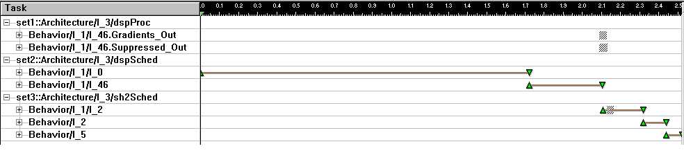
Fig. 8 - Image smoothing mapping results
The following is the set of mappings which were run
- Mapping everything to the SH2. This is the obvious starting point, so that we can see where bottlenecks in the system exist. The mapping was set up as shown below in Fig. 9.
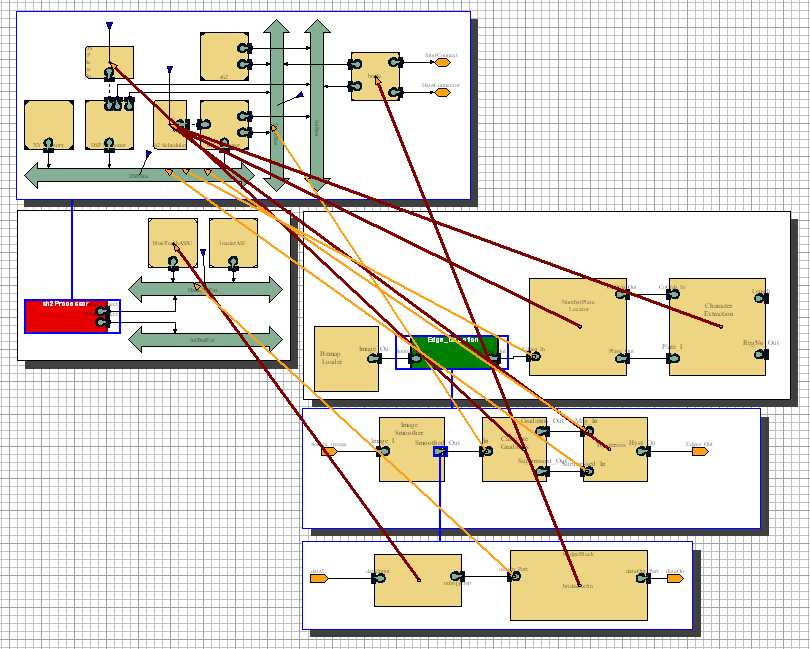
Fig. 9 - The initial mapping setup
We can quickly see from the results in Chart 1. that the Hysteresis block uses the largest processing time.
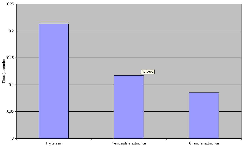
Chart 1 - Results from the SH2 mapping"
- Mapping the Hysteresis block to the DSP.
As a result, the next task was to try mapping the Hysteresis block to the DSP. This yielded the following results:
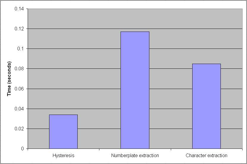
Chart 2. Results from the Hysteresis/DSP mapping
I am sure that you will agree that this is a large improvement! Also, because the two DSP-mapped blocks are next to each other in the behaviour, there is a significant point that there are no extra bus transfers over the previous map. So, the total time now to run the entire simulation has dropped from 1.309 seconds to 1.133 seconds, an improvement of over 13%.
Mapping to the TIGER Platform
Mapping of the TIGER Platform was carried out in much the same way as the above, with the initial mapping looking like Fig. 10.
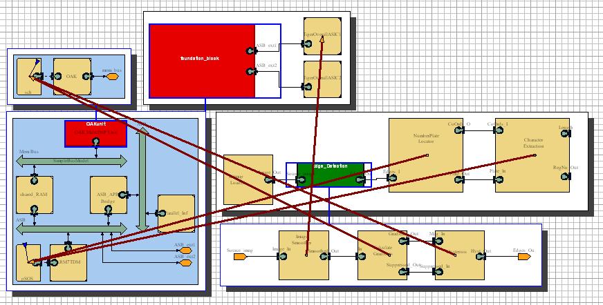
Fig 10 - The initial TIGER mapping
The thinking behind this initial mapping is that the very intensive image smoothing block is once again mapped to an outside ASIC because of its extremely long processing times when mapped to a processor unit. The other blocks are then mapped to the ARM or OAK respectively in the same way as to the SH2DSP setup previously.
Unfortunately, at this point we immediately hit a serious problem. Results from the ARM processor or from the OAK processor were possible, but when attempts were made to get results from both processors on a single Gantt chart one probe or the other continually produced no results, despite the fact that there must have been results being produced. Despite extensive attempts to repair these problems no real meaningful results for the overall behaviour could be obtained. However, the processing of the individual blocks can give us some idea of the relative performance of the TIGER architecture as a whole.
In particular, the performance of the hysteresis, numberplate finder and character extraction blocks are of interest when mapped to the equivalent processors in the SH2DSP architecture. The results obtained for these were as follows:
- Hysteresis: Mapped to the DSP: 0.004 seconds
- Numberplate Finder: Mapped to the ARM: 0.027 seconds
- Character Recognition: Mapped to the ARM: 0.024 seconds
Conclusions
Looking at the results obtained from the mappings of the two platforms we can come to some conclusions and also make a number of likely hypotheses that could be tested, given more time.
The obvious conclusion is that the TIGER platform appears to be must faster when the application is mapped to it. This is probably perfectly correct, and expected, since the faster ARM processor and OAK DSP are simply designed to operate faster than the SH2DSP setup. It would perhaps have been interesting to try these mapping comparisons against an SH3 or SH4 setup, which would be mrore likely to give competetive results.
Having said this, it should be noted that the SH2DSP setup is in no way producing bad results. The processors are making good progress in calculating the required data, and they are most likely perfectly fast for the purposes of our finished application.
Back to contents