SLIP Group C's Platform Modelling Diary Page
Main Index
Latest News
Historical Stuff
Application Page
Protocols Page
This page gives details of the platform modelling aspects of the System Level Integration Practical group C. Only one person is dealing with the platform modelling aspects of group C, Peter Johnston.
4/12/2000
After several demonstrations by our tutor, Jae, also attended by SLIP A's Simon Burrowes, I have managed to come up with a (very) basic architecture for the Hitachi SH2 platform which I am modelling. The model currently consists of a CPU unit with an RTOS scheduler, a section of memory, an integer-based data bus and an integer-based interrupt bus. I will put a diagram captured from VCC onto this page as soon as I can get at one of the SLI PCs in the Machine Halls.
Before I can get much further with the platform I am going to need two bits of information:
1: What the SH2 platform actually looks like. I need this to know what other components will need to be added to the platform.
2: What delays to give the processor instructions.
I will speak to Jae about both of these items at this afternoon's tutorial session.
11/12/2000
I have developed some more of the platform after consulting with Jae and getting hold of some copies from the sh2 manual. I think the model is now complete, but I'm not sure how to test it, so I am waiting on further input from tutor on this aspect.
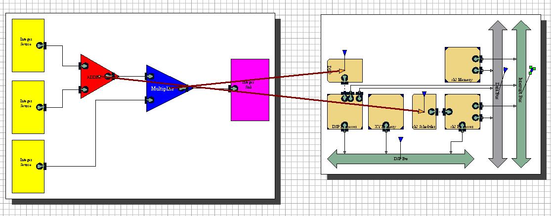
I do now have a screenshot to put up here (see below). This shows the untested initial platform model.
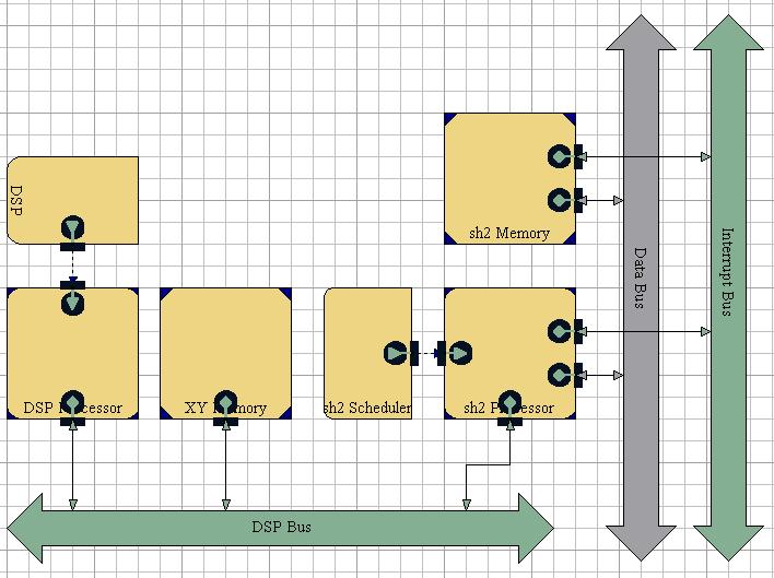
I have also generated the code sections for the processors, although these do not yet have valid timings to put into this to give an accurate simulation of the performance. However, I'm not worrying about this issue for the moment, being more interested in seeing the architecture doing something for real and giving a successful test with some behaviour(s).
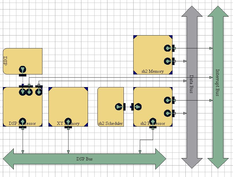
(later the same day)
After consulatation with Jae, the two extra connections were added, making the new platform look like the following:
12/1/2001
I now have the basis file to add to the platform model, and then it needs to be tested. This needs to be done by the end of next week in order to stick to the given deadlines for the course. This should hopefully be an achievable goal for me in the next few days. I intend to get the basis file in place today and then do the testing of the resulting model next week. I'll update this page as this work progresses.
15/1/2001
I have added the basis file (shown below) to the model of the platform. I have yet to run a successful test, though. I think I am going to need to speak to someone about this before I am going to make it work as I have a feeling I'm doing something fundamentally wrong with VCC. Perhaps Jae can help? Alternatively perhaps liasing with Alan may also help. He will have to know how to do this soon anyway, if we are to be running the testing later on this term.
The basis file is here.
19/1/2001
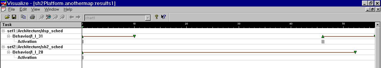
After an amount of debugging and fixing of the scheduler details for the processors I at long last have a functional architecture model which has produced some performance results in the form of a Gantt chart. The initial working mapping is shown below. This mapping only maps the basic behaviours to the architecture's processors. There is, as yet, no mapping of the communication routes, which will be the next step to a successful and more accurate model.
The Gantt charts that are created as a result of an analysis session with this mapping are shown below. We can see that the DSP processor ran between time units 0 and 10, and then again from time 46 to 56. The SH2 processor ran from time 0 to time 52.3.
Unfortunately Alan is not around the Machine Halls this afternoon to ask if the real application behaviour is ready to try plugging into the architecture. Hopefully, however, this will not be too difficult to get working on Monday. If all else fails, however, we should be able to demonstrate the models working with the simple behaviour that I have at the moment.
29/1/2001
This week I have tried to run some more mapping operations and probes in advance of trying to understand the results created by the VCC performance simulations. Unfortunately, the machine that I have been using (Irvine) has been crashing every time I try to run Visualize to look at the results. I have emailed Jae about this, but so far had no response.
My latest mapping and analysis session is shown in the image below.
later...
I have now managed to get the analysis results to visualize on another machine. Unfortunately they don't really tell me anything new at all. You can see from my mapping that I was trying to get results for the Gantt probes attached to the buses. This was in the hope that I could see which bus was being used when. However, when I try to compile the simulation I get the following error message:
Error:
* Current Simulation Time is: 0
Probe location '/(sh2Platform.anothermap:mapping)Architecture/(sh2Platform.sh2_arch:arch)DSP_Bus.BusGanttChart' is not present in the design. {in /(sh2Platform.anothermap:mapping)Architecture/(sh2Platform.sh2_arch:arch)sh2_sched/(VCC_Test.SchedulerGanttProbe:symbol)sh2SchedGantt/(sh2Platform.anothermap:mapping)ProbeModule}:
I don't currently understand what this error is telling me. It seems to be saying that the probe is attached to something that doesn't exist, which is blatently wrong. Perhaps I need to speak to the tutors about this.
Another thing that I have tried is to map some of the behaviours ports to the buses. However, this seems to create even more errors which I can't explain. I get an error message similar to the above. Perhaps this is because I am trying to map the wrong type of behaviour to the buses, and they can't handle it.
Hopefully soon Alan will have completed the application behaviour to a degree that allows us to try mapping it onto the architecture I have created. Then we can try to get some 'real' results. The application is currently not ready to map because much of the application code is in Blackbox C++.
5/2/2001
All in all, this week has not been wholly successful. I have spent a significant amount of time trying to get the communication mappings to work (partly in conjunction with Jae) and had very little success. It remains possible to get the simple add and multiply behaviours mapped to the two processors in the architecture. However, it should also be possible to map the ports in the behaviour to the appropriate buses in the architecture yet try as we might, we cannot make VCC accept the mapping of a port to the architecture. Add to this the further problem that Alan has not yet given me a copy of his application code that I can use to try mapping to the platform - presumably this is still due to the array problems he was having last week.
Jae and I have tried several approaches and ideas to try to make VCC accept a communication mapping. One is that the problems I was having last week with not being able to use a Gantt probe on a bus is related to the same problem as the mapping, and that it is therefore a bus implementation problem. Therefore, a whole new platform was built (using the existing components from the existing architecture) to try to create the buses in a different way. The VCC tutorial example of an electronic pager was used as a template to try to make this work.
There were some noticable differences between my original implementation of the architecture and the way in which it had been done in the pager example, and so the initial aim was to try to make the two identical and to see whether this solved the problems. This proved to be a time-consuming task, as the bus implementation is not particularly easy to understand, and with many bits that need to be set hidden in VCC. Eventually, however, it seemed to be complete. Unfortunately though, this did not solve the problems.
11/02/2001
I have been attempting to map the Bluetooth test stuff from the Bluetooth modelling group to my platform. As expected, this has not gone smootly. Several of the behaviours developed by the Bluetooth group appear not to have annotated c files associated with them, which makes things awkward since I need these for perormance modelling. I have therefore created these in the appropriate places (it requires no new code, so I'm not changing other people's implementations at all. This was working fine up until I came across a blackbox c++ code. This cannot be used in the performance modelling and therefore won't compile. I'll need to find out who has done this and ask them if there is a way around it. So far I have not had a successfull performance model compile, so this will have to be done quite soon.
Another thing that I need to do is speak to Jae about the communication mapping problems. I did manage to get a map to compile earlier this week with a communication mapping in place, however it didn't seem to generate any results when I attached a Gantt probe. Jae claims that he has managed some successful mappings now, though, so I should probably meet with him again and see how he has done this.
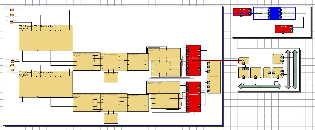
A screenshot of my attempted mapping with the Bluetooth setup is shown below:
26/2/2001
There has been, you'll notice, a short hiatus on updating this page. I have spent the time trying to map the bluetooth/tcp implementation to the platform, with a conspicuous lack of success, to be honest. Jae and I have spent several hours trying to map the bluetooth behaviours to the platform, and timing problems seem to abound all over the place.
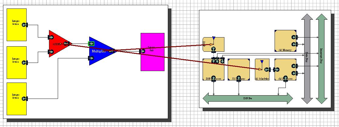
The good news, however, is the success in mapping the edge-recognition part of the application behaviour to the platform, complete with results. The mapping is shown below:
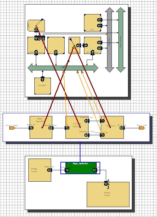
The behaviour consists of three blocks. The ones at each end are whitebox C, and middle one is blackbox C++. The blackbox model has a delay script associated with it to give the appropriate scheduler delay. Also, since the central block is the most computation-intensive, it is mapped to the DSP core. The others are both mapped to the sh2 processor.
The other three mappings give communication maps to the DSP bus, an 8 bit bus connecting the two processors. Gantt probes are attached to the two processor schedulers and the bus, and should show when the buses are in use.
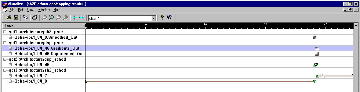
This first set of results shows the overall timeline of the simulation. It can be seen that the sh2 takes the most time in the simulation, followed by a burst from the DSP processor, and then more activity from the sh2. The four hashed areas show items that are currently too small to view. The top three show bus transfers, and the fourth, at the bottom, shows a short stop-start break in the sh2 activity.
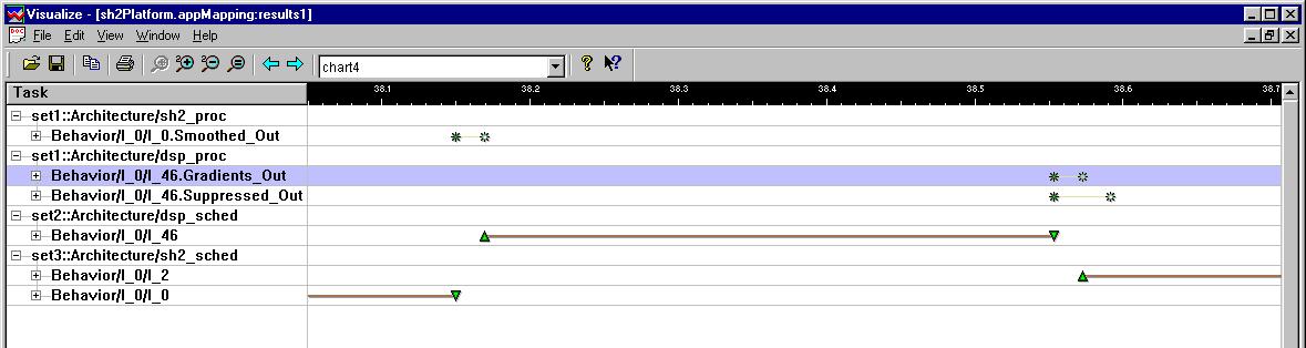
The second image of results show a zoomed in area of the above results, from (roughly) time 38.05 to 38.71 (times in milliseconds). These results show some of the previously hashed-out areas of results. We can now see the bus transfers, including two parallel transfers, which will have been arbitrated by the bus arbiter. The solid lines at the bottom of the results show the activity of the sh2 (at either side of the image) and the DSP (in the centre).
Page Maintained by Peter Johnston
Last Updated: 12th March 2001