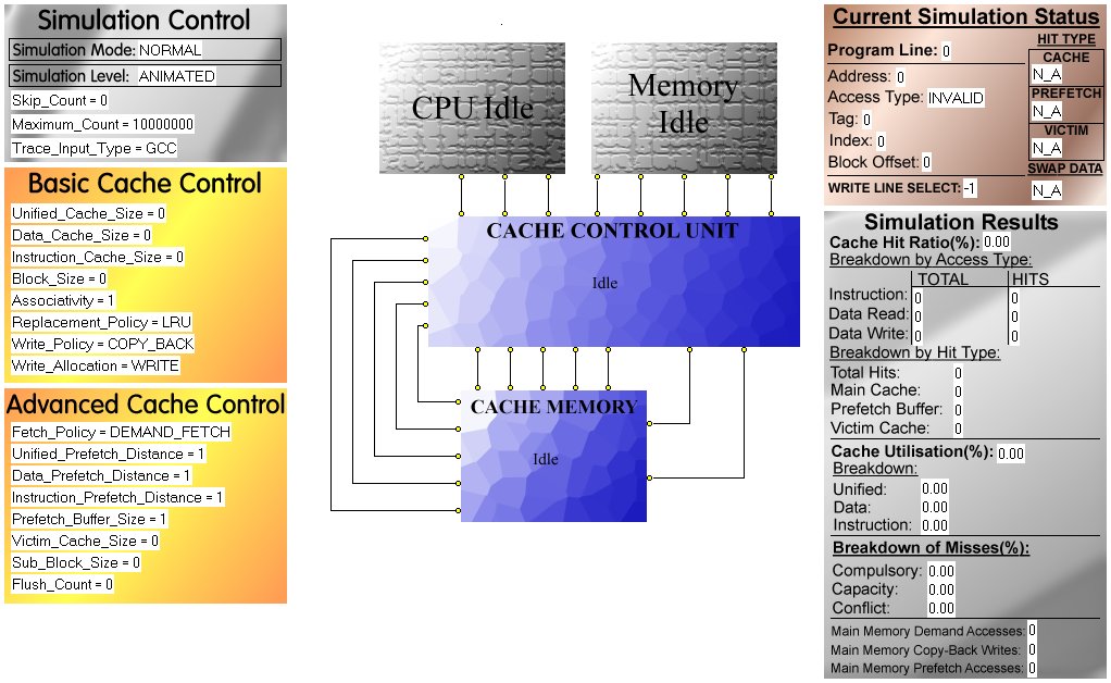
Simulation Control allows parameters affecting the simulation environment to be specified.
If set to one of the Tutorial modes an in-built tutorial will be simulated, which will result in all of the remaining simulation parameters being automatically set by HASE Dinero. To specify simulation parameters manually, ensure the simulation mode is set to Normal.
If set to Animated, the simulator will animate the display window during simulation playback. Note that there is a 500 line limit on the number of input trace file references that can be processed in Animated mode. If set to Fast, only the HASE Dinero results window will be updated after simulation playback, however there is a 10,000,000 line limit on the number of trace file references that can be processed.
This parameter specifies the first line in the input trace file that will be processed.
Specifies the highest trace file line number that will be processed during the simulation.
Allows the input trace file to be specified. HASE Dinero includes three default trace files: GCC, Spice and Latex. In addition the Custom type can be specified, which causes HASE Dinero to attempt to use a file called custom.trace, located in the root Dinero directory, as the input trace file.
The basic cache control allows fundamental cache parameters to be simulated. At least the cache size and block size parameters need to be modified from their default values for a valid cache configuration to be specified.
Each of these three parameters allows the size of the respective cache, in bytes, to be specified. Note that only one of either Unified OR (Data AND Instruction) caches can have positive values for any one cache configuration. Also, each cache size must be a power of 2. Note that no cache size can exceed 4KB in Animated Mode.
This allows the number of bytes to be stored on each cache line to be specified, and so must be less than the size of the smallest cache. The block size must be a power of 2. Note that block size cannot exceed 8 bytes in Animated Mode.
This parameter allows the size of the associative set to be specified. If set to one, a direct-mapped cache will be simulated. If set to 0, a fully-associative cache will be simulated. Any other positive value (up to a maximum of the number of lines in the smallest cache (which can be determined by: cache size / block size)) will result in a set-mapped cache. Associativity must be a power of 2.
The replacement policy determines how lines are selected to be overwritten, when a new block is loaded to the cache, if there are no free cache lines. One of Least Recently Used (LRU), First-In First-Out (FIFO) or Random can be chosen.
The write policy specifies whether CPU writes should immediately propagate to main memory (Write-Through) or should instead be stored in the cache only (Copy-Back).
If set to Write then all CPU writes are written to the cache. If set to No Write then no CPU writes are stored in the cache. Note that if the Write Policy is set to copy-back then a write allocation policy of no write is not allowed.
The advanced cache control allows various cache hit optimisation strategies to be experimented with.
The fetch policy defaults to Demand Fetch, in which main memory is only ever accessed if data required by the CPU is not stored in the cache. If set to Always Prefetch then every trace file reference processed results in a prefetch operation occurring. If set to Miss Prefetch then a prefetch operation occurs after every cache miss. Forward Prefetch only works with sub-block placement, and specifies that any sub-block prefetches that would result in a sub-block outside of the current block being fetched will be aborted. Sub-Block Prefetch only works if sub-block placement is enabled, and specifies that any prefetch command specifying a sub-block outside of the current block should instead be converted to a sub-block prefetch inside the current block by a simple wrapping method. Note that prefetching operations are only carried out for data read or instruction fetch trace references.
Allows the size of the prefetch stride to be specified for each cache type. The prefetch stride is specified in terms of blocks (or sub-blocks if sub-block placement is enabled). Note that if the fetch policy is set to sub-block or forward, then no prefetch distance can be greater than the number of sub-blocks in a block.
Allows the size of the circular FIFO prefetch buffer to be specified in terms of the number of (sub-) blocks it can contain. Note that a single prefetch buffer contains the prefetch data for all simulated caches. There is a 100 entry limit on the size of the prefetch buffer.
If set to a positive value, enables the victim cache. The victim cache size is specified in terms of the number of (sub-) blocks it can hold. There is a 100 entry limit on the size of the victim cache.
If set to a positive value, enables sub-block placement. The sub-block size is specified in bytes and must be a power of 2. The sub-block size must be less than the block size. Note that sub-blocks cannot be simulated in Animated Mode.
This can be used to crudely simulated multiprogramming by specifying how frequently the entire cache contents should be invalidated, in terms of the number of intermediary input trace file references processed.
The CPU is the source of trace file references supplied to the cache. All data written by the CPU is specified by a negative byte sequence number.
Main memory supplies data to the cache in the event of a cache miss. All data supplied to the cache by main memory has a positive byte sequence number.
The cache control unit is the heart of the cache simulation. It receives trace file references from the CPU and checks the cache memory to determine whether a hit has occurred, loading the required data from main memory on cache misses. The cache control unit is also responsible for enforcing all cache configuration policies. Right-clicking with the mouse on the cache control unit whilst HASE is in simulate mode allows the contents of the prefetch buffer and victim cache to be viewed. Note that any HASE array has to be opened before commencing simulation playback in order for the array contents to be correctly shown and updated.
The left-to-right format of data stored in the prefetch buffer and victim cache is as follows:
The cache for which the stored data is valid, one of:
|
|||||||
The validity of the stored data, one of:
|
|||||||
| The cache index value for which the stored data is valid | |||||||
| The cache tag value for which the stored data is valid | |||||||
| The remaining entries in each line correspond to the sequence numbers of bytes stored in the data block |
The Cache Control Unit has 25 possible states, each of which uses the following colour-coding scheme:
| Blue: Idle | |
| Green: Read Data | |
| Red: Write Data | |
| Orange: Write to Main Memory, Update Cache | |
| Yellow: Send Data to CPU | |
| Pink: Prefetch Buffer Operation | |
| Cyan: Victim Cache Operation | |
| Black: Flush Cache |
The cache memory array provides the data storage capability of the simulated cache. By right clicking on the cache memory array whilst HASE is in simulate mode, the contents of the unified, data and instruction cache can be viewed. Note that any HASE array has to be opened before commencing simulation playback in order for the array contents to be correctly shown and updated.
The left-to-right format of data stored in the cache contents windows is as follows:
The validity of the cache line, one of:
|
|||||
The modified status of the cache line, one of:
|
|||||
| The timestamp of the cache line, which is set every time the cache line is accessed | |||||
| The tag field of the address of the block stored in the cache line | |||||
| The remaining entries in each line correspond to the sequence numbers of bytes stored in the cache line block |
The status window is only active during Animated Mode simulation playback. The window displays information on the current cache status and activity.
The program line indicates the current trace file reference being processed in terms of how many references have already been processed.
The hexadecimal value of the current trace reference being serviced by the cache. The address is split into its constituent components (note that an explanation of how these components are calculated can be found in the Guide to Use section):
| Access Type. Indicates the type of the memory reference (e.g.: data read, data write or instruction fetch). | |
| Tag. Indicates the tag component of the address. | |
| Index. Indicates the index component of the address. | |
| Block Offset. Indicates the block offset component of the address. |
If the cache control unit is currently updating the status fields of a cache line, or writing a new block to the cache, the write line select field indicates which line will be modified.
This section of the status screen indicates whether a cache hit has occurred to one of: the main cache, prefetch buffer or victim cache. Note that each potential cache hit location has one of four status values:
| YES. A hit has occurred to this location | |
| NO. A hit has not occurred to this location | |
| WAIT. The cache control unit is in the process of determining whether a cache hit has occurred. | |
| N/A. A cache hit cannot occur to this location due to the cache configuration being simulated. |
This value indicates whether a modified line in the cache will need to be written to main memory as a consequence of the current cache activity. The swap data field can take one of four values:
| YES. Data does need to be swapped out to main memory | |
| NO. Data does not need to be swapped out to main memory | |
| WAIT. The cache control unit is in the process of determining whether data needs to be swapped to main memory | |
| N/A. The cache write policy is set to write-through, and so no cache lines can have their modified bits set. |
The results window provides a detailed breakdown of the current simulation results in both Animated and Fast modes of operation. The results windows is dynamically updated for every trace file references in Animated mode.
This is probably the most important cache performance metric, indicating the percentage of the trace file references processed that have resulted in a cache hit.
This section provides information on both the precise number of trace file references that have been processed so far for each of the three main types (data read, data write and instruction fetch), and the number of cache hits for each type of trace reference.
This section indicates the precise number of cache hits that have occurred. The total number of hits is broken down into the three potential hit locations: the main cache prefetch buffer and victim cache.
The cache utilisation performance metric indicates how well the loading of new blocks to the cache is distributed. For an explanation of how the cache utilisation is calculated, see the Guide to Use.
This is the most complex of the performance metrics. Each of the three components of the miss breakdown (compulsory, capacity and conflict) sum to 100%. For an explanation of how the miss breakdown is calculated, see the Guide to Use.
The three values in this section of the results screen indicate the total number of accesses that have been made to main memory by the cache control unit. The values indicate the number of memory accesses in terms of loaded (sub-) blocks.
| Demand Accesses are caused by (sub-) blocks being loaded from main memory to service a cache miss. | |
| Copy-Back Writes are caused by a modified cache block being discarded from the cache and hence written to main memory. | |
| Prefetch Accesses are caused by every prefetch operation that occurs. |
![]()